Introduction: Start with the Cooling Load, Not the Coil Dimensions
Selecting the right refrigeration evaporator requires more than matching a coil to a room size, compressor horsepower, or existing equipment dimensions. The evaporator must deliver the required cooling capacity under the actual operating conditions of the refrigeration system.
For OEMs, refrigeration system integrators, cold-room manufacturers, and replacement-equipment buyers, the most important question is not simply, “What size evaporator do I need?” It is:
What evaporator can provide the required cooling capacity at my design evaporating temperature, refrigerant, airflow or fluid conditions, and operating load?
A coil that appears suitable on paper may deliver insufficient capacity if its published rating was determined under different conditions. Conversely, selecting a much larger unit without evaluating airflow, refrigerant distribution, controls, and operating cycles does not automatically improve system performance.
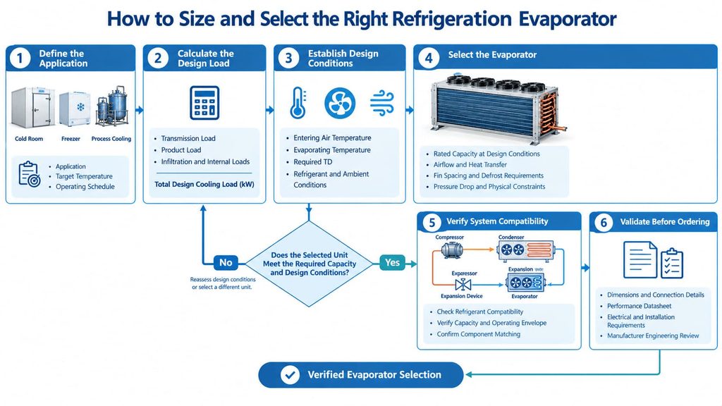
A reliable refrigeration evaporator sizing process follows six steps:
- Determine the application’s total refrigeration load.
- Define the design conditions and operating requirements.
- Select an evaporator with sufficient capacity at those specific conditions.
- Verify temperature difference, airflow, heat-transfer area, and pressure drop.
- Confirm compatibility with the compressor, condenser, expansion device, and refrigerant.
- Verify the manufacturer’s performance data before placing an order.
This guide explains how to calculate the cooling load, evaluate evaporator sizing requirements, avoid common selection errors, and prepare the technical information needed for an accurate quotation.
1. What Is Refrigeration Evaporator Sizing?
Refrigeration evaporator sizing is the process of determining the required heat-transfer capacity and selecting an evaporator that can meet the cooling demand under specified operating conditions.
The process involves two related but different tasks:
- Cooling-load calculation: Determining how much heat must be removed from the refrigerated space, product, or process.
- Evaporator selection: Identifying a heat exchanger that can remove that amount of heat at the specified refrigerant conditions, entering-medium temperatures, flow rates, and other design constraints.
Confusing these two tasks is one of the most common causes of incorrect evaporator selection.

1.1 What Does an Evaporator Do in a Refrigeration System?
The evaporator absorbs heat from the space or material being cooled. Refrigerant enters the heat exchanger at a low pressure and temperature, absorbs heat, and typically evaporates as it passes through the coil.
In an air-cooling application, a fan moves air across the evaporator surface. Heat transfers from the air through the coil wall into the refrigerant.
In a liquid-cooling application, heat transfers from the process liquid through a heat-exchanger surface into the refrigerant.
The evaporator therefore needs sufficient heat-transfer capability to meet the required load without violating the system’s operating limits.
For a broader explanation of component functions, see our refrigeration evaporator design and selection guide and guide to how a refrigeration evaporator works.
1.2 Evaporator Capacity vs. Refrigeration Load
These terms are related, but they are not interchangeable.
| Parameter | Meaning | How it is used |
|---|---|---|
| Refrigeration load | Heat that must be removed from the application | Establishes the required cooling duty |
| Evaporator rated capacity | Cooling capacity published for specified test or operating conditions | Allows engineers to compare candidate models |
| Actual evaporator capacity | Capacity available at the real operating conditions | Determines whether the selected unit can meet the load |
| Compressor refrigeration capacity | Cooling capacity the compressor can support under specified operating conditions | Must be checked against the evaporator and system duty |
| Condenser heat-rejection capacity | Heat that must be rejected from the refrigeration circuit | Includes the evaporator load and compressor energy added to the refrigerant, subject to the system boundary |
A critical purchasing rule follows from this distinction:
Do not compare a calculated refrigeration load with a catalogue capacity until you have checked the conditions under which that capacity is rated.
For example, an evaporator rated at a particular capacity at one evaporating temperature may not provide the same capacity at a lower evaporating temperature or under different entering-air conditions.
1.3 Why Nominal Capacity Alone Is Not Enough
A product specification may list a nominal capacity, coil dimensions, fan quantity, and connection size. Those details are useful, but they do not fully define performance.
At a minimum, confirm:
- Refrigerant type.
- Refrigerant evaporating temperature and corresponding pressure.
- Condensing conditions and available system capacity.
- Entering-air or entering-fluid temperature.
- Airflow or fluid flow rate.
- Required outlet temperature.
- Temperature difference between the cooled medium and refrigerant.
- Frosting, defrost, humidity, and operating-cycle requirements.
- Allowable pressure drop and installation limitations.
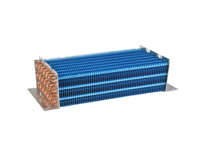
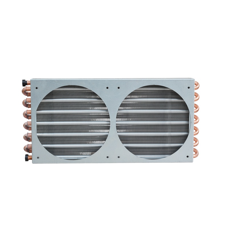
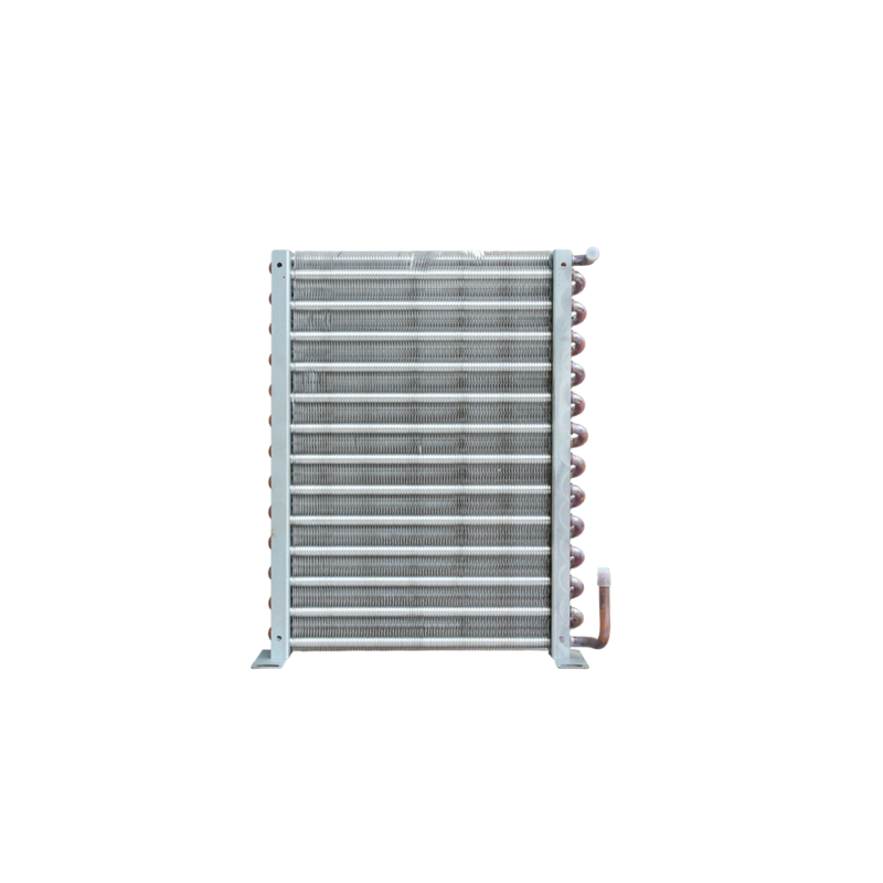
Two evaporators with similar dimensions can have different capacities because of differences in tube arrangement, fin spacing, heat-transfer surface, circuiting, airflow, and refrigerant distribution.
2. What Information Do You Need Before Sizing an Evaporator?
Before performing a refrigeration evaporator sizing calculation, establish the design conditions. Missing or inconsistent inputs can make even a mathematically correct calculation unsuitable for equipment selection.
2.1 Define the Application and Required Cooling Conditions
Start by identifying what must be cooled and how the system will operate.
| Information | Questions to answer | Why it matters |
|---|---|---|
| Application | Cold room, freezer, process chiller, or another system? | Determines the relevant load sources and evaporator configuration |
| Target temperature | What temperature must the space, product, or fluid reach? | Establishes the cooling requirement |
| Initial temperature | What is the temperature before cooling begins? | Affects product or process load |
| Cooling time | How quickly must the target temperature be achieved? | Determines the required cooling rate |
| Operating schedule | Continuous, intermittent, or batch operation? | Affects peak load and duty-cycle evaluation |
| Load profile | Is the load constant or variable? | Helps establish design and part-load requirements |
| Ambient conditions | What are the expected maximum and typical conditions? | Affects heat gain, airflow, and equipment performance |
For a cold room, the load may vary significantly with door openings, product deliveries, product temperature, and internal equipment operation.
For a process-cooling application, the most important inputs may instead be fluid flow rate, inlet temperature, outlet temperature, production schedule, and process variability.
Do not size an evaporator solely from the room’s floor area or volume unless a validated method appropriate to the application supports that approach.
2.2 Collect the Main Refrigeration Design Parameters
The refrigeration circuit must be evaluated under a consistent set of design conditions.
The required information may include:
- Refrigerant designation.
- Design evaporating temperature.
- Condensing temperature or pressure.
- Required refrigerant mass flow, if available.
- Compressor model and performance data.
- Expansion-device type and control range.
- Required superheat and liquid subcooling conditions.
- Suction-line pressure drop and other relevant circuit losses.
The evaporating temperature is especially important. It is the refrigerant’s saturation temperature associated with the operating pressure, rather than the temperature of the refrigerated room or process fluid.
The refrigerant’s state and properties also matter. A capacity calculation for one refrigerant cannot simply be transferred to another refrigerant without checking the relevant thermodynamic properties and equipment ratings.
2.3 Identify Heat-Transfer and Installation Constraints
For air-cooled evaporators, determine the available airflow, fan arrangement, entering-air temperature, humidity, required air distribution, and installation clearance.
For liquid-cooling evaporators, identify the fluid composition, flow rate, inlet and outlet temperatures, pressure drop limits, material compatibility, and fouling risks.
For either type, document:
- Available installation envelope.
- Connection type and orientation.
- Design pressure and temperature limits.
- Corrosion or contamination exposure.
- Service access and cleaning requirements.
- Frost and defrost requirements, where applicable.
These constraints should be identified before comparing models. A technically suitable evaporator is of little value if it cannot fit the installation or operate reliably under the site’s conditions.
3. How to Calculate the Required Refrigeration Load
The refrigeration load represents the rate at which heat enters the refrigerated space, product, or process and must be removed to maintain the required conditions.
A complete calculation should include all significant load sources relevant to the application.

3.1 Identify the Main Sources of Heat Load
3.1.1 Transmission Load
Transmission load is heat entering through walls, floors, ceilings, doors, and other boundaries because of a temperature difference.
A simplified steady-state calculation is:
[
Q_{\text{trans}}=U A \Delta T
]
Where:
- (Q_{\text{trans}}) = transmission heat load, W.
- (U) = overall heat-transfer coefficient, W/(m²·K).
- (A) = heat-transfer area, m².
- (\Delta T) = temperature difference across the boundary, K.
For example, assume a cold-room boundary has:
- Area: 80 m².
- Overall heat-transfer coefficient: 0.25 W/(m²·K).
- Temperature difference: 25 K.
Then:
[
Q_{\text{trans}}=0.25\times80\times25=500\text{ W}
]
This is an illustrative calculation for one boundary. A real design must calculate the relevant walls, ceiling, floor, doors, thermal bridges, and other applicable heat paths separately.
3.1.2 Product or Process Load
Product load is the heat that must be removed from material entering the refrigerated space.
For sensible cooling without a phase change:
[
Q_{\text{product}}=\frac{m c_p \Delta T}{t}
]
Where:
- (m) = product mass, kg.
- (c_p) = specific heat capacity, kJ/(kg·K).
- (\Delta T) = product temperature reduction, K.
- (t) = cooling time, seconds.
The equation gives the average cooling load in kW when (c_p) is expressed in kJ/(kg·K) and time is in seconds.
For example, assume an industrial application must cool 500 kg of a material from 20°C to 5°C in two hours. Assume a specific heat capacity of 3.8 kJ/(kg·K).
[
Q_{\text{product}}=
\frac{500\times3.8\times15}{7200}
]
[
Q_{\text{product}}\approx3.96\text{ kW}
]
This calculation estimates the average sensible cooling rate for the stated assumptions.
It is not a complete evaporator sizing result. Depending on the application, additional loads may include packaging, trays, containers, moisture removal, phase change, heat transfer within the product, and variations in the cooling rate over time.
3.1.3 Infiltration and Ventilation Load
Warm air entering a refrigerated space carries both sensible and, where moisture is involved, latent heat.
For a simple air-stream calculation, the sensible component can be approximated by:
[
Q_{\text{sensible}}=\dot m_{\text{air}}c_p\Delta T
]
Where:
- (\dot m_{\text{air}}) = air mass flow rate, kg/s.
- (c_p) = air specific heat capacity, kJ/(kg·K).
- (\Delta T) = air temperature difference, K.
For moist-air infiltration, a more complete calculation uses the difference in moist-air enthalpy:
[
Q_{\text{air}}=\dot m_{\text{air}}(h_{\text{outside}}-h_{\text{inside}})
]
The enthalpy difference accounts for both sensible and latent effects when the air properties and units are defined consistently.
For cold rooms and freezers, the actual infiltration load depends on door-opening frequency and duration, pressure differences, air curtains, traffic, outside humidity, and the volume of air exchanged. A single arbitrary allowance may not represent these conditions adequately.
3.1.4 Internal and Operational Loads
Other load sources may include:
- Lighting.
- Fan motors and other equipment located in the refrigerated space.
- People entering the space.
- Conveyors, pumps, and production machinery.
- Defrost heat that must be removed after the defrost cycle, where relevant.
- Other application-specific heat sources.
Only include the loads that apply to the system being designed. Avoid double-counting heat already included in another calculation.
3.2 Refrigeration Load Calculation Formula
For an application with several independent load sources, the total load can be represented as:
[
Q_{\text{total}}=
Q_{\text{trans}}+
Q_{\text{product}}+
Q_{\text{infiltration}}+
Q_{\text{internal}}+
Q_{\text{other}}
]
The equation is a load-accounting framework, not a substitute for identifying the actual sources of heat gain.
The units must be consistent. If all components are calculated in kW, the total is also in kW.
The final design should distinguish between:
- Average operating load.
- Peak or design load.
- Load during pull-down or initial cooling.
- Load during steady-state operation.
- Load during or following defrost, where applicable.
These conditions do not necessarily occur simultaneously. The design duty should reflect the actual operating sequence rather than blindly adding every possible maximum value.
3.3 Convert the Total Load into a Design Requirement
Once the load is calculated, determine the required design cooling duty and any justified allowance for uncertainty or operating variation.
A simple planning expression is:
[
Q_{\text{design}}=Q_{\text{calculated}}(1+S)
]
Where (S) is a selected allowance expressed as a decimal.
For example, if a calculated load is 12 kW and an illustrative 10% allowance is justified:
[
Q_{\text{design}}=12\times1.10=13.2\text{ kW}
]
The 10% figure is only an example, not a universal refrigeration design rule. The appropriate allowance depends on load uncertainty, operating requirements, design standards, and the consequences of insufficient capacity.
A large, unexplained safety factor can lead to unnecessary equipment cost or poor system matching. A small factor can leave the system unable to meet peak demand. The correct approach is to document the assumptions behind the design requirement.
3.4 Worked Example: Calculate a Product Cooling Load
Consider a hypothetical process that cools 500 kg of material from 20°C to 5°C over two hours.
Assumptions:
| Parameter | Value |
|---|---|
| Product mass | 500 kg |
| Specific heat capacity | 3.8 kJ/(kg·K) |
| Temperature reduction | 15 K |
| Cooling time | 2 h |
| Calculated average product load | 3.96 kW |
Suppose the other independently calculated loads are:
| Load source | Illustrative value |
|---|---|
| Transmission | 0.50 kW |
| Product cooling | 3.96 kW |
| Infiltration | 0.70 kW |
| Internal equipment and lighting | 0.40 kW |
| Other documented loads | 0.30 kW |
| Total calculated load | 5.86 kW |
If a justified design allowance of 10% is applied for this illustrative example:
[
Q_{\text{design}}=5.86\times1.10
]
[
Q_{\text{design}}\approx6.45\text{ kW}
]
The result is a preliminary design cooling requirement of approximately 6.45 kW under the stated assumptions.
It does not mean that any evaporator labelled 6.45 kW will be suitable.
The next step is to identify a model that can deliver the required capacity at the specified refrigerant, evaporating temperature, entering-medium conditions, airflow or fluid flow, and other applicable rating conditions.
If the manufacturer’s published capacity is based on a different set of conditions, obtain a corrected selection or a performance rating for the actual design point.
4. How to Select Evaporator Capacity from the Calculated Load
After determining the required cooling duty, the task becomes a performance-selection problem.
4.1 Match the Required Capacity to Actual Operating Conditions
When comparing evaporator models, ask the manufacturer to confirm capacity at the intended operating point.
The selection should identify:
- Required net cooling capacity.
- Refrigerant and evaporating temperature.
- Entering-air or entering-fluid conditions.
- Required outlet conditions, where relevant.
- Airflow or fluid flow rate.
- Pressure drop.
- Defrost and operating-cycle assumptions, where applicable.
If a catalogue lists several capacities, do not assume the largest listed value applies to your installation. A capacity may be tied to a particular temperature difference, refrigerant, flow condition, or test method.
The comparison is valid only when the rating conditions are understood.
4.2 Understand Evaporator TD and Temperature Difference
For an air-cooling evaporator, TD commonly refers to the temperature difference between the entering air and the refrigerant evaporating temperature under a defined rating condition.
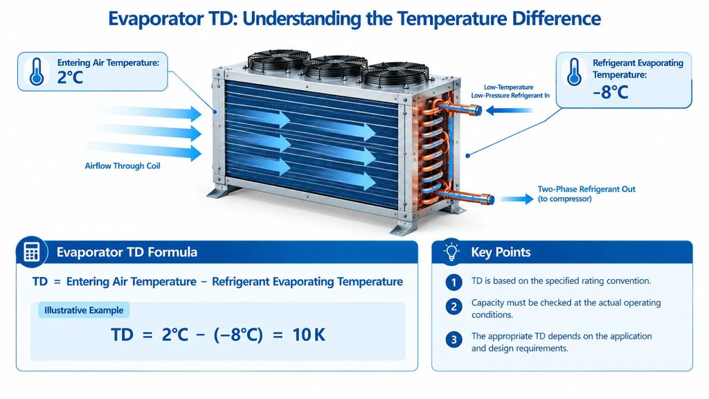
A simplified expression is:
[
TD=T_{\text{air,in}}-T_{\text{evap}}
]
Where:
- (T_{\text{air,in}}) = entering air temperature.
- (T_{\text{evap}}) = refrigerant evaporating saturation temperature.
For example, if entering air is 2°C and the refrigerant evaporating temperature is −8°C:
[
TD=2-(-8)=10\text{ K}
]
This is an illustrative temperature difference, not a recommendation for every application.
For a liquid-cooling evaporator, the relevant temperature differences and rating method may be different. A liquid heat exchanger should be evaluated using its specified inlet and outlet conditions and the manufacturer’s performance method.
Why TD matters
The temperature difference influences the driving force for heat transfer. For a given duty and other conditions, changing the temperature difference can change the required heat-transfer surface and the resulting equipment selection.
However, a larger TD does not automatically mean a better design. In air-cooling applications, a larger difference may be associated with a lower evaporating temperature relative to the room, potentially affecting compressor performance and product temperature conditions.
A smaller TD may require more heat-transfer surface or a different coil configuration. The final choice depends on the required cooling conditions, equipment cost, airflow, humidity, and whole-system energy performance.
4.3 Why Lower Evaporating Temperatures Can Change Capacity and Energy Use
The evaporating temperature affects refrigerant pressure and the compressor’s operating conditions.
For many vapor-compression systems, lowering the evaporating temperature increases the pressure ratio and can reduce compressor refrigeration capacity while increasing the energy required per unit of cooling. The magnitude depends on refrigerant properties, compressor design, condensing conditions, and operating limits.
This creates an important selection trade-off.
If the application requires a low product temperature, selecting a higher evaporating temperature merely to improve compressor performance may prevent the system from meeting its cooling requirement.
Conversely, choosing a lower evaporating temperature than necessary may increase energy consumption without providing a useful application benefit.
The correct evaporating temperature must therefore be established from the required product or process conditions, heat-transfer approach, and system design—not selected independently to make the evaporator appear more powerful.
4.4 Check Airflow, Heat-Transfer Area, and Pressure Drop
For air-cooled evaporators, capacity depends on more than the coil’s external dimensions.
Important factors include:
- Heat-transfer surface area.
- Tube arrangement and refrigerant circuiting.
- Fin geometry and spacing.
- Airflow rate and distribution.
- Fan performance and power.
- Air-side pressure drop.
- Refrigerant-side pressure drop.
- Coil cleanliness and frosting behaviour.
Higher airflow can improve air-side heat transfer in some conditions, but it can also increase fan power and pressure drop. The relationship is not linear across all operating points.
Similarly, tighter fin spacing may provide more surface area in a given volume but can increase sensitivity to frost accumulation in low-temperature applications.
For liquid-cooling evaporators, flow velocity, fluid properties, heat-transfer coefficients, fouling, and allowable pressure drop are important selection variables.
The manufacturer’s performance data should be used to assess the combined effect of these parameters.
5. How Evaporator Type and Application Affect Sizing
There is no single sizing procedure that can be applied identically to every refrigeration application. The load calculation framework may be similar, but the heat-transfer and operational constraints differ.
5.1 Air-Cooled Evaporators for Cold Rooms and Freezers
Air-cooled evaporators transfer heat from circulating air to the refrigerant.
Selection requires attention to:
- Room temperature and required product temperature.
- Entering-air temperature and humidity.
- Air circulation and distribution.
- Required cooling capacity at the specified TD.
- Fan quantity, airflow, and power.
- Fin spacing and frost accumulation.
- Defrost method and recovery time.
- Installation clearance and service access.
A coil with sufficient clean-condition capacity may not maintain the same performance throughout a low-temperature operating cycle if frost significantly restricts airflow.
For this reason, low-temperature evaporator sizing should consider not only initial heat-transfer performance but also the operating cycle between defrost periods.
5.2 Water-Cooled and Liquid-Cooling Evaporators
For liquid-cooling applications, the required heat-transfer duty can often be estimated from the fluid mass flow and temperature change:
[
Q=\dot m c_p(T_{\text{in}}-T_{\text{out}})
]
Where:
- (Q) = heat removed, kW when units are consistent.
- (\dot m) = fluid mass flow rate, kg/s.
- (c_p) = fluid specific heat capacity, kJ/(kg·K).
- (T_{\text{in}}-T_{\text{out}}) = fluid temperature reduction, K.
For example, consider a water-like fluid with a mass flow rate of 0.5 kg/s, a specific heat capacity of approximately 4.18 kJ/(kg·K), and a temperature reduction of 5 K.
[
Q=0.5\times4.18\times5=10.45\text{ kW}
]
This estimates the heat removed from the fluid under the stated assumptions. It does not establish the required heat-exchanger model by itself.
The final selection must also verify fluid properties, heat-transfer area, refrigerant conditions, pressure drop, material compatibility, and any fouling or corrosion concerns.
If the process fluid is a glycol mixture, oil, or another fluid with different properties, use the appropriate specific heat and viscosity data rather than assuming water values.
5.3 Industrial Process Refrigeration Applications
Industrial systems may experience variable production loads, batch cycles, or continuous operation under demanding conditions.
The sizing process should identify:
- Normal and peak process loads.
- Required product or process outlet temperatures.
- Permissible temperature variation.
- Production cycle and pull-down time.
- Fouling or contamination risks.
- Cleaning and maintenance intervals.
- Redundancy requirements, where applicable.
A process with a highly variable load may require a different control and capacity strategy from a process operating steadily at a constant duty.
If the system must maintain a critical process temperature during peak demand, the selection should explicitly address that requirement rather than relying only on average load.
5.4 Low-Temperature Freezer Applications
Low-temperature freezer evaporators require particular attention to frost and defrost.
Key variables include:
- Design evaporating temperature.
- Product and room temperatures.
- Humidity and infiltration.
- Fin spacing.
- Airflow and fan operation.
- Defrost type, duration, and frequency.
- Capacity available after accounting for the operating cycle.
The impact of frost depends on the application and operating conditions. It should not be represented by a universal correction percentage without supporting equipment data or a validated design method.
For freezer evaporator sizing, request performance information appropriate to the specified low-temperature conditions and defrost strategy.
6. How to Match an Evaporator with the Compressor, Condenser, and Expansion Device
An evaporator is not an independent cooling source. It is one part of a refrigeration circuit in which component performance is interdependent.
Component-balancing and refrigeration-system design material that reflects the importance of evaluating the equipment as a system.
6.1 Evaporator and Compressor Matching
The compressor must be able to circulate sufficient refrigerant and provide the required refrigeration capacity under the specified operating conditions.
Check:
- Refrigerant type.
- Evaporating and condensing temperatures.
- Compressor capacity at the intended operating point.
- Compressor operating envelope.
- Refrigerant mass flow and suction conditions.
- Superheat and oil-return requirements, where applicable.
Compressor horsepower alone is not enough to establish compatibility.
Two compressors with the same nominal motor rating may have different refrigeration capacities because of differences in displacement, refrigerant, operating pressures, and design.
The evaporator should therefore be selected against the compressor’s performance data at the actual operating point.
6.2 Evaporator and Condenser System Balance
The condenser rejects heat absorbed by the evaporator plus the energy added to the refrigerant by compression, subject to the system configuration and heat-balance boundary.
In a simplified steady-state refrigeration circuit:
[
Q_{\text{cond}}\approx Q_{\text{evap}}+W_{\text{comp}}
]
Where:
- (Q_{\text{cond}}) = condenser heat-rejection duty.
- (Q_{\text{evap}}) = evaporator cooling duty.
- (W_{\text{comp}}) = compressor energy transferred to the refrigerant.
This is a simplified heat balance; real system calculations must account for the applicable system boundary and additional heat transfers.
It explains why the evaporator and condenser cannot simply be assumed to have equal nominal capacities.
For related engineering background, see our refrigeration condenser sizing and selection guide and complete refrigeration cycle guide.
6.3 Expansion Device and Refrigerant Feed
The expansion device regulates refrigerant flow into the evaporator according to the system design and control strategy.
A mismatch between the evaporator and expansion device can contribute to poor refrigerant distribution, unstable superheat, insufficient capacity, or liquid-management problems.
Selection should verify:
- Refrigerant compatibility.
- Required capacity and operating range.
- Available pressure difference.
- Evaporator circuit configuration.
- Control method and sensing arrangement.
- Manufacturer requirements for refrigerant feed and superheat control.
A correctly sized heat exchanger cannot compensate for every problem caused by unsuitable refrigerant feed or system controls.
6.4 What Happens When Components Are Mismatched?
Possible symptoms depend on the specific fault and operating conditions.
| Potential mismatch | Possible effect | What to investigate |
|---|---|---|
| Evaporator capacity below required duty | Inability to maintain the required temperature under design load | Load calculation, rating conditions, airflow or fluid flow |
| Compressor capacity inconsistent with evaporator duty | Unstable operation or inability to meet design conditions | Compressor performance map and system operating point |
| Incorrect expansion-device selection | Poor refrigerant feed or unstable superheat | Refrigerant, capacity, pressure difference, control requirements |
| Excessive airflow resistance | Reduced airflow and potential capacity loss | Fan curve, coil pressure drop, frost and installation clearance |
| Inadequate condenser performance | Higher condensing pressure or reduced system performance under affected conditions | Condenser rating, ambient conditions, airflow or water flow |
| Incompatible replacement coil | Installation difficulties or incorrect operating performance | Dimensions, connections, refrigerant, pressure rating and capacity data |
These are diagnostic possibilities, not guaranteed outcomes. A system-level evaluation is necessary before assigning a cause.
7. Common Evaporator Sizing Mistakes and How to Avoid Them
7.1 Selecting by Physical Dimensions Alone
A replacement coil may fit the available space but fail to meet the original performance requirements.
External dimensions do not fully define heat-transfer area, internal circuiting, refrigerant distribution, fan performance, or pressure drop.
Better approach: Compare the operating conditions and rated performance first, then verify the mechanical envelope and connections.
7.2 Using the Wrong Rating Conditions
A catalogue capacity may be quoted at an evaporating temperature or entering-air condition that differs from the application.
This can lead to an incorrect comparison between candidate products.
Better approach: Ask for capacity at the actual design point or obtain manufacturer-supported selection data for the intended conditions.
7.3 Ignoring Frost, Defrost, and Operating Cycles
For low-temperature applications, clean-coil capacity alone may not describe the system’s performance throughout the operating cycle.
Frost can restrict airflow, while defrost temporarily changes the system’s heat balance and cooling availability.
Better approach: Confirm the intended defrost strategy, frost conditions, and capacity requirements during normal operation and recovery.
7.4 Oversizing or Undersizing Without a Load Analysis
An undersized evaporator may fail to meet peak demand. An oversized unit can increase purchase and installation cost and may introduce airflow, control, or system-matching issues if the overall design is not adjusted accordingly.
Oversizing does not automatically reduce energy use, and undersizing does not always produce the same symptoms in every system.
Better approach: Calculate the load, document the design allowance, and verify the selected model’s performance under the specified conditions.
7.5 Failing to Verify Replacement Compatibility
For replacement projects, the original equipment label may not provide all the information required for a reliable selection.
Confirm:
- Refrigerant and operating pressure.
- Required cooling capacity and rating conditions.
- Coil dimensions and connection positions.
- Tube and fin materials.
- Fan voltage, frequency, and electrical requirements.
- Mounting, drainage, and service access.
- Control and defrost requirements.
If the original model number is available, provide it to the supplier, but do not assume a visually similar replacement is technically equivalent.
8. How Correct Evaporator Sizing Affects Energy Efficiency and Service Life
Evaporator sizing influences energy performance through its effect on heat transfer, operating temperatures, airflow, and the behaviour of the wider refrigeration system.
It is not possible to assign one universal energy-saving percentage to correct sizing. The outcome depends on the existing system, operating schedule, component selection, controls, and application conditions.
8.1 Heat-Transfer Performance and Operating Temperatures
The selected evaporator must provide the required duty at an appropriate evaporating temperature.
If the heat exchanger requires a substantially lower refrigerant temperature to deliver the design load, compressor performance may be affected. Conversely, a larger heat-transfer surface may allow the required duty to be achieved under different operating conditions, but the actual benefit must be confirmed by performance calculations.
The relevant comparison is therefore the performance of the complete refrigeration system at equivalent load and operating conditions—not simply the nominal capacity of two coils.
8.2 Fan Power, Pressure Drop, and Defrost Requirements
For air-cooled evaporators, fan energy is part of the overall operating cost.
The selection should balance airflow, heat transfer, pressure drop, fan power, noise, and frost behaviour.
A design with a high airflow rate is not automatically the most efficient. The fan operating point and the coil’s air-side resistance must be considered together.
For low-temperature equipment, defrost energy and the time required to recover cooling capacity may also affect overall performance.
8.3 Maintenance Access and Long-Term Reliability
Correct sizing also means choosing a unit that can be inspected, cleaned, and maintained under the actual operating conditions.
Relevant considerations include:
- Access to coil surfaces and drain systems.
- Corrosion resistance.
- Frost accumulation and defrost access.
- Fan and motor replacement.
- Spare-part availability.
- Operating pressure and temperature limits.
These factors may influence lifecycle cost even when two products have similar initial prices.
For OEMs and replacement buyers, a technically documented selection is often more valuable than a low initial quotation that does not clearly state its performance conditions.
9. Evaporator Sizing Checklist for OEMs and Replacement Buyers
The fastest route to a useful quotation is to provide a complete set of operating conditions rather than asking for an evaporator based only on dimensions or nominal capacity.
When replacing an existing evaporator, matching the original dimensions is only the starting point. Buyers should also verify the refrigerant, capacity at the required operating conditions, connection sizes, airflow, fin spacing, defrost requirements, and installation constraints. Our guide to replacement refrigeration evaporator coil compatibility and selection explains the key checks to complete before ordering.
9.1 Technical Information Required for Evaporator Selection
Use the following checklist when preparing an RFQ.
| Information | What to provide |
|---|---|
| Application | Cold room, freezer, process cooling, or other use |
| Required cooling capacity | kW or BTU/h, including the design basis |
| Refrigerant | Exact refrigerant designation |
| Evaporating condition | Design evaporating temperature or pressure |
| Condensing condition | Condensing temperature or pressure, if available |
| Entering-medium condition | Air or liquid inlet temperature and relevant environmental conditions |
| Required outlet condition | Target air, product, or fluid temperature |
| Airflow or fluid flow | Required flow rate and any operating constraints |
| Pressure drop | Allowable air-side or fluid/refrigerant-side pressure drop, where specified |
| Installation | Available dimensions, mounting, orientation, and connection details |
| Materials | Required tube, fin, casing, and corrosion-resistance characteristics |
| Operating cycle | Hours, load variation, pull-down, frost, and defrost requirements |
| Existing equipment | Model number, nameplate, photographs, drawings, and datasheets |
| Compliance | Applicable certification, safety, and project requirements |
Not every application will require every item. However, the more complete the technical input, the easier it is to determine whether a proposed model is suitable.
9.2 What to Check in a Manufacturer’s Evaporator Datasheet
Before approving a selection, confirm that the datasheet clearly identifies:
- Rated cooling capacity and the conditions under which it was determined.
- Refrigerant and applicable operating range.
- Evaporating temperature and relevant entering-medium conditions.
- Airflow or fluid flow rate.
- Pressure drop and other important hydraulic or aerodynamic data.
- Dimensions, connection specifications, and materials.
- Fan and electrical data, where applicable.
- Defrost configuration and operating limitations, where relevant.
- Any correction factors, assumptions, or exclusions used in the rating.
If two suppliers provide different capacity figures, first compare their rating conditions and calculation assumptions. A difference in published numbers does not necessarily indicate that one product is better.
9.3 When to Request Engineering Review
A manufacturer or qualified refrigeration engineer should review the selection when:
- The operating conditions differ substantially from standard catalogue ratings.
- The application involves low-temperature or demanding industrial operation.
- The refrigerant or operating pressure requires special consideration.
- The system load varies significantly.
- A replacement project lacks complete original equipment data.
- The installation has strict space, noise, airflow, or pressure-drop limits.
- The consequences of insufficient cooling capacity are significant.
The purpose of an engineering review is to verify the performance and compatibility assumptions before purchase—not simply to recommend the largest available model.
10. Frequently Asked Questions About Refrigeration Evaporator Sizing
How Do You Calculate Refrigeration Evaporator Capacity?
Start by calculating the total application heat load, including relevant transmission, product or process, infiltration, and internal loads. Establish the design duty, then select an evaporator whose rated capacity meets that requirement at the actual refrigerant and operating conditions.
A load calculation alone does not identify the correct product model. Manufacturer performance data are needed to verify the selection.
What Size Evaporator Do I Need for My Refrigeration System?
The required size depends on the cooling load, refrigerant, evaporating temperature, entering-medium conditions, airflow or fluid flow, and installation constraints.
The most reliable method is to calculate the required duty and request a model selection at the specified operating point. Room volume or compressor horsepower alone is not sufficient for a dependable selection.
How Does Evaporator TD Affect Sizing?
For an air-cooling evaporator, TD commonly describes the difference between entering-air temperature and refrigerant evaporating temperature under a defined rating condition.
TD influences the heat-transfer driving force and can affect the required surface area and operating conditions. The appropriate value depends on the application, humidity, target temperature, equipment design, and energy-performance objectives.
How Do You Match an Evaporator to a Compressor?
Compare the evaporator’s required cooling duty with the compressor’s available refrigeration capacity at the specified refrigerant, evaporating temperature, condensing temperature, and suction conditions.
Also verify refrigerant flow, operating limits, expansion-device compatibility, and the wider system design. Nominal horsepower alone does not establish a correct match.
Can an Evaporator Be Too Large for a Refrigeration System?
Yes, an evaporator can be unsuitable if it is selected without considering airflow, refrigerant distribution, controls, operating conditions, installation limits, and system balance.
However, a larger heat exchanger is not inherently a problem. The important question is whether the complete system has been designed and controlled to operate correctly with the selected component.
What Information Is Needed to Select a Replacement Evaporator Coil?
Provide the existing model number or datasheet if available, required cooling capacity, refrigerant, evaporating conditions, airflow, dimensions, connections, materials, and defrost requirements.
For a reliable replacement, verify rated performance and system compatibility rather than relying on visual similarity or external dimensions alone.
Does Evaporator Sizing Affect Energy Efficiency?
Yes. The selected evaporator influences heat transfer, operating temperatures, airflow, fan power, and potentially defrost requirements. These factors interact with compressor and condenser performance.
The energy effect must be evaluated for the complete refrigeration system under comparable loads and operating conditions. There is no universal energy-saving percentage that applies to every correctly sized evaporator.
Conclusion: Size the Evaporator for the Actual System Conditions
Reliable refrigeration evaporator sizing begins with an accurate understanding of the application’s cooling load. The next step is to select a heat exchanger that can meet that duty at the intended evaporating temperature, refrigerant, entering-medium conditions, and airflow or fluid-flow requirements.
The main principles are straightforward:
- Calculate the required cooling duty before choosing a product.
- Compare rated capacities only when their operating conditions are understood.
- Evaluate TD, heat-transfer area, airflow, pressure drop, frosting, and defrost requirements where applicable.
- Verify compatibility with the compressor, condenser, expansion device, and controls.
- Review the manufacturer’s datasheet and confirm the operating point before ordering.
For OEMs, system integrators, and replacement-equipment buyers, this approach helps reduce avoidable selection errors and makes supplier quotations more meaningful.
Need Help Selecting a Refrigeration Evaporator?
Looking for a refrigeration evaporator that matches your application and operating conditions?
Share your required cooling capacity, refrigerant, evaporating temperature, airflow or fluid conditions, installation dimensions, and other technical requirements. If you are replacing an existing unit, include the original model number, nameplate, drawings, or datasheet whenever available.
Our team can review the information provided and discuss a suitable evaporator configuration for your project.
Contact us for refrigeration evaporator selection and quotation to discuss your technical requirements.