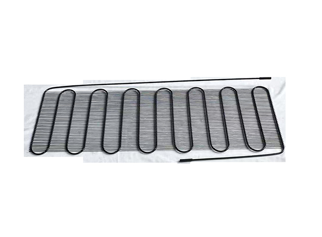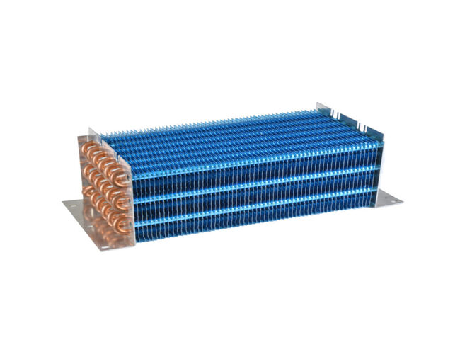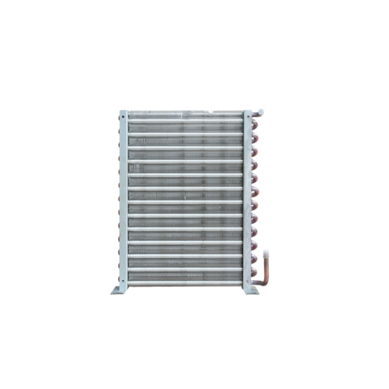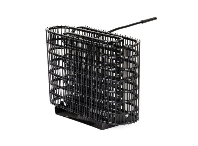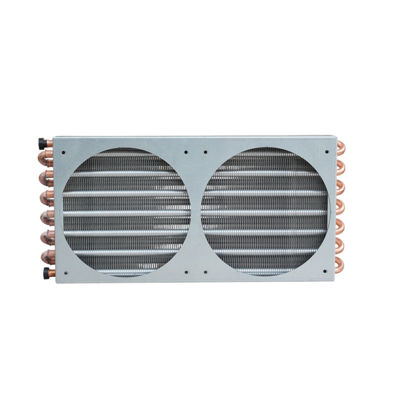
An evaporator coil and a condenser coil may look similar because both transfer heat through tubes, fins, or other heat-transfer surfaces. However, they perform different jobs, operate under different refrigerant conditions, and must be designed around different thermal and mechanical requirements.
For refrigeration equipment manufacturers, OEMs, system integrators, distributors, and engineering procurement teams, the difference matters most when specifying a new component or sourcing a replacement. A coil that fits the available space is not necessarily a coil that can deliver the required capacity, refrigerant distribution, pressure drop, or operating reliability.
The key distinction is simple: an evaporator coil absorbs heat from the medium being cooled, while a condenser coil rejects heat from the refrigerant to a warmer surrounding medium. The engineering decisions behind each component, however, involve much more than heat-flow direction.
This guide compares evaporator coils and condenser coils from a refrigeration engineering and B2B purchasing perspective. It explains their working principles, construction, design differences, common performance problems, and the information required to specify a compatible replacement.
1. What Is the Difference Between an Evaporator Coil and a Condenser Coil?
An evaporator coil and a condenser coil are both heat exchangers used in refrigeration systems, but they perform opposite thermal functions.
The evaporator transfers heat into the refrigerant, allowing the refrigerant to absorb energy from air, water, or another process medium. The condenser transfers heat out of the refrigerant, allowing the refrigerant to release energy to air, water, or another heat-rejection medium.
The two components work together, but they are not interchangeable by default.
Evaporator Coil vs. Condenser Coil: At-a-Glance Comparison
| Comparison point | Evaporator coil | Condenser coil |
|---|---|---|
| Primary function | ਠੰਢੇ ਕੀਤੇ ਮਾਧਿਅਮ ਤੋਂ ਗਰਮੀ ਸੋਖ ਲੈਂਦਾ ਹੈ | Rejects heat from the refrigerant |
| Heat-flow direction | Cooled medium → refrigerant | Refrigerant → cooling medium |
| Main refrigerant process | Boiling or evaporation at low pressure | Desuperheating and condensation at high pressure; subcooling may follow |
| Typical refrigerant inlet condition | Low-pressure liquid-vapor mixture in many expansion-fed systems | High-pressure, high-temperature vapor from the compressor |
| Typical refrigerant outlet condition | Vapor, often with some superheat depending on design | Liquid, often with some subcooling depending on design |
| Main thermal design concern | Delivering required cooling capacity at the specified evaporating condition | Rejecting the total system heat load at the specified condensing condition |
| Air-side considerations | Airflow, fin spacing, frost risk, moisture removal, and defrost where applicable | Airflow, ambient temperature, heat rejection, fouling, and possible air recirculation |
| Refrigerant-side considerations | Distribution, pressure drop, boiling performance, and outlet superheat | Pressure drop, condensation performance, liquid drainage, and outlet subcooling |
| Common applications | Cold rooms, display cases, process chillers, refrigerated equipment, and industrial cooling | Condensing units, commercial refrigeration systems, industrial refrigeration equipment, and process cooling systems |
| Replacement priorities | Capacity at design conditions, refrigerant compatibility, circuiting, dimensions, airflow, and defrost requirements | Total heat rejection, design ambient conditions, refrigerant, circuiting, pressure drop, airflow or water flow, and connections |
The table describes common vapor-compression refrigeration arrangements. Exact refrigerant states and design requirements depend on the system architecture, refrigerant, expansion device, control strategy, and operating conditions.
Is a Condenser Coil the Same as an Evaporator Coil?
No. They may share construction methods, materials, and manufacturing processes, but their thermal duties are different.
For example, a finned-tube evaporator may be designed to operate below the freezing point of water. It may therefore require fin spacing and defrost provisions suited to frost formation. A condenser in the same system may operate above the surrounding air temperature and must reject heat under the expected maximum ambient condition.
Even if both coils use copper tubes and aluminum fins, differences in tube circuiting, surface area, fin geometry, refrigerant distribution, pressure rating, and connections can make them unsuitable for substitution.
A useful purchasing rule is:
Treat visual similarity as a starting point for identification, not proof of engineering compatibility.
What Is the Difference Between a Coil and a Complete Heat Exchanger?
In refrigeration purchasing, the terms coil, heat exchanger, evaporator, and ਕੰਡੈਂਸਰ can overlap, but they do not always describe the same supply scope.
A coil commonly refers to the heat-transfer assembly made from tubes, fins where applicable, headers, and refrigerant connections. Depending on the design, it may be supplied as a bare coil or as part of a larger assembly.
A complete evaporator or condenser assembly may also include a casing, fan or fans, drain pan, defrost equipment, guards, controls, supports, or other components.
A complete heat exchanger may use a different construction, such as a plate, shell-and-tube, or tube-in-tube arrangement rather than a finned coil.
When requesting a quotation, define the required supply scope. A quote for a bare replacement coil is not necessarily comparable with a quote for a complete, tested assembly.
2. What Is a Coil in a Refrigeration System?
What Is a Refrigeration Coil?
A refrigeration coil provides a surface through which heat can move between the refrigerant and another medium. That medium may be air, water, glycol solution, or another process fluid, depending on the equipment design.
In an air-cooled coil, refrigerant flows through tubes while air passes over the external surfaces. Fins are often attached to the tubes to increase the area available for heat transfer. In other designs, the refrigerant and secondary fluid exchange heat through plates, shells, or other surface geometries.
Heat transfer depends on several interacting factors:
- The temperature difference between the refrigerant and the medium being cooled or heated.
- The effective heat-transfer surface area.
- Heat-transfer coefficients on the refrigerant and secondary-fluid sides.
- Refrigerant and air or water flow rates.
- Flow arrangement, circuiting, and distribution.
- Fouling, frost, corrosion, and other changes during service.
A common simplified heat-transfer relationship is:
Q = U × A × ΔTₘ
ਕਿੱਥੇ:
- Q = heat-transfer rate, typically expressed in watts or kilowatts.
- U = overall heat-transfer coefficient.
- A = effective heat-transfer area.
- ΔTₘ = appropriate mean temperature difference between the two sides.
This equation is useful for understanding the relationship between capacity, surface area, and temperature difference. It is not, by itself, a complete coil-sizing method. Real coil selection may require refrigerant property data, heat-transfer and pressure-drop correlations, airflow or fluid-flow calculations, and performance testing.
The equation also explains why increasing surface area alone does not guarantee a satisfactory replacement. A coil may have more area but still perform poorly if refrigerant distribution, airflow, pressure drop, or operating conditions are unsuitable.
Common Components of a Refrigeration Coil
Tubes and Refrigerant Passages
Tubes or internal passages carry the refrigerant through the heat exchanger. Their material, diameter, wall thickness, arrangement, and internal geometry affect heat transfer, pressure drop, mechanical strength, and compatibility with the refrigerant and lubricant.
Tube selection cannot be based on diameter alone. The refrigerant, design pressure, tube material, operating temperature, joining method, and applicable requirements must all be considered.
Fins and Heat-Transfer Surface
Fins increase the surface area available for heat exchange with air. Their geometry influences air-side pressure drop, heat-transfer performance, cleanability, and the effect of dirt or frost.
Fin pitch is particularly important in applications exposed to moisture or freezing conditions. Closely spaced fins can provide a large surface area in a compact volume, but they may be more vulnerable to blockage when frost, dust, grease, or other deposits accumulate.
Wider fin spacing may be more appropriate for certain low-temperature evaporators, but the correct arrangement depends on the application, operating conditions, airflow, and defrost strategy. There is no universal fin spacing suitable for every evaporator or condenser.
Headers, Distributors and Circuiting
Headers and distributors direct refrigerant into and out of the coil circuits. Circuiting determines how the refrigerant travels through the available tubes and how the heat-transfer surface is used.
An unsuitable circuit arrangement may cause uneven refrigerant distribution, excessive pressure drop, insufficient utilization of the surface area, or unstable performance. In multi-circuit coils, the interaction between the refrigerant distribution system and the available load is particularly important.
This is one reason why copying the external dimensions of an existing coil may not reproduce its original performance.
Connections, Supports and Mounting Features
Connections include refrigerant inlets and outlets, tube stubs, headers, and other interfaces required by the system. Their dimensions, orientation, position, and joining requirements must match the installation.
Supports and mounting features affect vibration resistance, mechanical stability, installation clearance, and service access. Drainage provisions and casing geometry may also be important for evaporators that collect condensate or undergo defrost cycles.
For replacement work, record connection size and orientation rather than relying on a photograph alone.
Where Are Evaporator and Condenser Coils Located?
Their physical locations depend on the equipment design.
| Equipment or application | Typical evaporator location | Typical condenser location |
|---|---|---|
| Domestic refrigerator | Inside the refrigerated cabinet or behind internal panels | Often near the compressor or integrated into the cabinet structure; layouts vary |
| Commercial display cabinet | Within the refrigerated air circuit, often behind an internal panel | In the condensing unit or a separate heat-rejection section |
| Cold-room system | Inside the cold room or in the air cooler serving it | In a separate condensing unit, often outdoors or in a designated plant area |
| Industrial process refrigeration | In the chiller, process cooler, or equipment serving the process load | In the refrigeration plant or a separate air-, water-, or evaporatively cooled assembly |
| Refrigerated production equipment | Near the product or process cooling circuit | In the equipment’s designated heat-rejection section |
In a domestic refrigerator, the condenser may be visible at the rear or bottom, but some designs conceal it within the cabinet structure. Commercial and industrial systems may use remote condensers, water-cooled condensers, or other configurations.
For B2B sourcing, the important question is not simply where the coil sits. It is how the coil connects to the refrigerant circuit and the medium that transfers heat to or from it.
3. What Is a Refrigeration Evaporator Coil?
What Is the Primary Function of an Evaporator Coil?
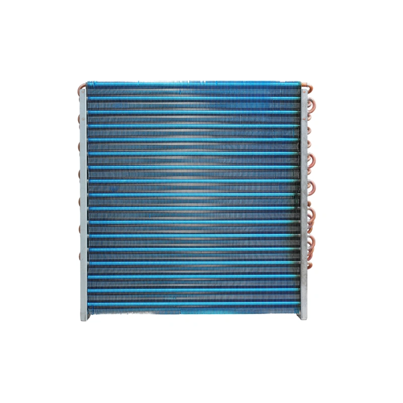
The primary function of an evaporator coil is to absorb heat from the medium that needs to be cooled.
In an expansion-fed vapor-compression system, the refrigerant pressure is reduced before the refrigerant enters the evaporator. At the resulting low-pressure condition, the refrigerant can absorb heat and boil at a temperature lower than that of the surrounding air or process fluid.
The heat absorbed by the evaporator is the useful refrigeration effect. It may be used to cool a cold room, preserve food, chill a liquid, control a manufacturing process, or maintain a required temperature in commercial equipment.
Evaporator performance must therefore be assessed against the actual cooling duty. A coil that works in one application may not achieve the same capacity in another if the evaporating temperature, airflow, entering-medium temperature, refrigerant, or operating schedule changes.
How Does an Evaporator Coil Work?
Low-Pressure Refrigerant Enters the Coil
In many direct-expansion systems, refrigerant passes through an expansion device before entering the evaporator as a low-pressure liquid-vapor mixture.
The exact inlet condition depends on the system design and expansion process. The refrigerant’s pressure and saturation temperature establish the conditions under which it can absorb heat from the surrounding medium.
Heat Transfer from the Cooled Medium to the Refrigerant
Air, water, glycol, or another process medium passes over or through the heat exchanger. Heat moves from the warmer medium, across the heat-transfer surface, and into the colder refrigerant.
The refrigerant must remain at a sufficiently low temperature relative to the medium for heat to flow in the required direction. If the temperature difference is too small, the coil may not deliver the required capacity without additional surface area or changes to the operating conditions.
Refrigerant Boils and Absorbs Latent Heat
As heat enters the refrigerant, part of the liquid boils into vapor. During this phase change, the refrigerant absorbs latent heat.
The boiling process is a major part of the heat absorption in many conventional evaporators. Its performance depends on the refrigerant properties, local pressure, mass flow, heat flux, internal flow conditions, and the way refrigerant is distributed through the coil.
An evaporator must be designed so that its surface is used effectively while keeping pressure drop and refrigerant distribution within acceptable limits.
Refrigerant Vapor Leaves the Coil
At the evaporator outlet, the refrigerant is commonly vapor. Depending on the design and control strategy, it may leave with a degree of superheat.
The outlet condition matters because it influences refrigerant management, compressor protection, capacity, and system stability. An evaporator should not be selected only by its nominal capacity or physical size; its outlet behavior must also suit the rest of the refrigeration system.
Why Evaporator Coil Temperature and Airflow Matter
An evaporator operates in response to the temperature and flow conditions on both sides of the heat-transfer surface.
For an air-cooling evaporator, important variables include:
- Entering air temperature and humidity.
- Required leaving air or product temperature.
- Evaporating temperature and refrigerant.
- Airflow rate and air distribution.
- Coil face area, fin spacing, and tube arrangement.
- Condensate drainage and defrost requirements.
- Refrigerant distribution and pressure drop.
Illustrative example: Suppose a cold-room application requires an air temperature of 2°C while the evaporating temperature is −8°C. The nominal difference between these temperatures is 10 K. This is a simplified temperature-difference example, not a coil selection specification. Actual capacity also depends on humidity, airflow, refrigerant properties, coil geometry, and the temperature distribution through the coil.
If the required room temperature remains unchanged but the design evaporating temperature is reduced, the available temperature difference may increase. However, the system’s compressor capacity and power consumption may also change. A larger temperature difference does not automatically mean a lower total operating cost.
In low-temperature applications, frost can accumulate on the air side when the surface is below freezing and moisture is present. Frost increases resistance to airflow and heat transfer. Consequently, fin spacing, defrost method, operating duration, and condensate management are important parts of evaporator design.
For a more detailed explanation of evaporator operation, thermal performance, sizing, and component selection, see our refrigeration evaporator design and selection guide.
What Are the Common Types of Evaporator Coils?
Evaporator designs vary according to the medium being cooled, temperature range, capacity, installation, and refrigeration architecture.
| Evaporator type or configuration | Typical application | Important selection considerations |
|---|---|---|
| Finned-tube air evaporator | Cold rooms, display cases, air coolers, and refrigerated equipment | Airflow, fin spacing, frost formation, defrost, and refrigerant distribution |
| Liquid chiller evaporator | Process cooling and chilled-water or glycol systems | Fluid flow, approach temperature, pressure drop, fouling, and freeze protection |
| Shell-and-tube evaporator | Industrial and commercial liquid cooling | Refrigerant/fluid arrangement, tube-side or shell-side conditions, cleaning, and design pressure |
| Plate heat exchanger used as an evaporator | Compact liquid-cooling systems and selected industrial applications | Channel distribution, pressure drop, fluid compatibility, and serviceability |
| Custom OEM evaporator coil | Equipment built around specific space and operating requirements | Dimensions, connections, performance requirements, circuiting, materials, and assembly interfaces |
Not every supplier manufactures every type. Buyers should confirm that the manufacturer can supply the required construction and that the product is intended for the actual application.
For projects involving a finned-tube replacement, see our refrigeration evaporator coils product and the more detailed [replacement refrigeration evaporator coils buyer’s guide]. The buyer’s guide should be used for the full replacement-compatibility checklist, while this comparison article focuses on how evaporator and condenser coils differ.
4. What Is a Refrigeration Condenser Coil?
What Is the Primary Function of a Condenser Coil?
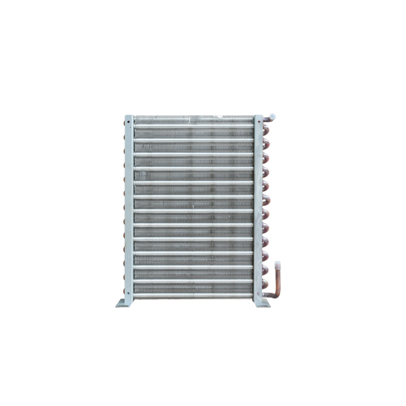
A condenser coil rejects heat from the refrigerant to a surrounding medium, usually air or water. In a typical vapor-compression system, the compressor sends high-pressure, high-temperature refrigerant vapor into the condenser.
The condenser removes heat from that vapor until the refrigerant condenses into liquid. Depending on the design, the refrigerant may then be cooled below its saturation temperature at the relevant pressure, a process known as subcooling.
A condenser must reject more heat than the evaporator absorbs because compressor energy also enters the refrigeration cycle. For a simplified steady-state system:
Condenser heat rejection = Evaporator cooling load + Compressor power input
This energy balance is central to condenser selection. A condenser should not automatically be sized using the evaporator’s cooling capacity alone.
How Does a Condenser Coil Work?
Hot Refrigerant Vapor Enters the Condenser
The compressor raises the refrigerant pressure and delivers hot vapor to the condenser. The refrigerant enters at a condition that allows it to release heat to the cooler surrounding medium.
The inlet temperature, pressure, refrigerant, mass flow, and compressor operating point influence the required heat-rejection duty.
Superheated Vapor Releases Sensible Heat
When the refrigerant enters the condenser as superheated vapor, it may first cool toward its saturation temperature. This part of the process is known as desuperheating.
The amount of heat removed in this region depends on the refrigerant state and the design. It should not be assumed that every condenser has the same proportion of surface dedicated to desuperheating.
Refrigerant Condenses and Releases Latent Heat
Once the refrigerant reaches the relevant saturation condition, vapor condenses into liquid as heat continues to leave the refrigerant.
In many conventional condensers, condensation accounts for a substantial part of the total heat rejection. Condenser heat transfer, capacity, pressure drop, and the influence of operating conditions on selection. Its examples illustrate why condenser ratings must be tied to specified conditions rather than treated as universal capacity values.
Further Cooling May Produce Subcooled Liquid
Some condenser designs continue cooling the liquid refrigerant below its saturation temperature at the local pressure. This is called subcooling.
Subcooling can help ensure that liquid refrigerant reaches the expansion device without unwanted vapor formation in the liquid line. The required amount depends on the system design, line pressure drop, refrigerant, operating conditions, and expansion device.
More subcooling is not automatically better in every configuration. It must be evaluated as part of the complete system design.
Why Condenser Coil Temperature and Heat Rejection Matter
A condenser’s capacity depends on the temperature difference between the refrigerant and the cooling medium, as well as the heat-transfer surface and flow conditions.
For an air-cooled condenser, important factors include:
- Maximum design ambient dry-bulb temperature.
- Saturated condensing temperature at the design operating point.
- Total heat rejection rather than evaporator load alone.
- Airflow rate, fan performance, and air recirculation.
- Coil surface area, fin geometry, and refrigerant circuiting.
- Refrigerant pressure drop and required outlet condition.
- Fouling, corrosion, and installation restrictions.
A condenser installed in a hot, poorly ventilated equipment enclosure may perform differently from the same coil installed outdoors with unrestricted airflow. Recirculation of hot discharge air can raise the air temperature entering the coil and reduce its effective temperature difference.
Condenser selection depends on the cooling medium, design temperatures, required heat rejection, flow rates, space, and operating pressure. Its guidance also emphasizes the impact of condensing conditions on compressor operation.
For a broader engineering discussion of condenser types, heat rejection, sizing, and selection, read our refrigeration condenser selection guide.
What Are the Common Types of Condenser Coils?
| Condenser type | Heat-rejection medium | Typical application | Main selection considerations |
|---|---|---|---|
| Air-cooled finned-tube condenser | ਆਲੇ-ਦੁਆਲੇ ਦੀ ਹਵਾ | Commercial condensing units and many refrigeration systems | Design ambient, airflow, fan arrangement, heat rejection, and fouling |
| Water-cooled condenser | Water or another specified cooling fluid | Industrial plants and systems with suitable cooling-water infrastructure | Water temperature and flow, fouling, water-side pressure drop, corrosion, and maintenance |
| Evaporative condenser | Water and air, using evaporative heat rejection | Selected industrial and commercial refrigeration plants | Entering wet-bulb condition, water quality, airflow, water management, and maintenance |
| Shell-and-tube condenser | Typically water on one side and refrigerant on the other | Industrial and commercial refrigeration | Heat rejection, flow arrangement, design pressure, water quality, and cleanability |
| Custom OEM condenser coil | Depends on equipment configuration | Equipment manufacturers and specialized refrigeration applications | Capacity, installation envelope, refrigerant, materials, connections, and operating conditions |
The term condenser coil is often used for a finned-tube air-cooled condenser, but a condenser does not have to be a finned coil. Water-cooled and evaporative condenser arrangements may use different heat-exchanger constructions.
If your application requires a custom finned-tube condenser or a replacement component, start with the required heat-rejection duty and operating conditions, then verify the physical and mechanical interfaces. Do not select a replacement solely by matching the old coil’s length and height.
5. How Do Evaporator and Condenser Coils Work Together in a Refrigeration System?
The Refrigeration Cycle from Evaporation to Condensation
In a conventional vapor-compression refrigeration system, the evaporator and condenser form part of a cycle that also includes a compressor and an expansion device.
- Evaporation: The refrigerant absorbs heat in the evaporator and leaves as vapor under the conditions established by the system design.
- Compression: The compressor raises the refrigerant pressure and typically increases its temperature.
- Condensation: The condenser rejects heat to the cooling medium and converts the refrigerant vapor into liquid.
- Expansion: The expansion device reduces the refrigerant pressure before it returns to the evaporator.
The cycle repeats as long as the system operates and the required operating conditions can be maintained.
To understand how the evaporator, compressor, condenser, and expansion device interact throughout the cycle, read our complete refrigeration cycle engineering guide.
How the Two Coils Affect Overall System Performance
The evaporator determines how effectively heat is collected from the cooled medium. The condenser determines how effectively the system can reject the collected heat plus the energy added by the compressor.
Neither component should be evaluated in isolation.
For example, a condenser that cannot reject the required heat at the design ambient temperature may cause condensing pressure and compressor power to rise. Depending on the system and controls, cooling capacity may fall or protective controls may stop operation.
An evaporator with unsuitable capacity or refrigerant distribution may fail to meet the required cooling load, operate with unstable outlet conditions, or use its heat-transfer surface inefficiently.
The system also depends on the compressor, expansion device, piping, refrigerant charge, controls, and operating environment. A coil change may therefore require system-level verification rather than a simple component swap.
A Worked Example: Why Condenser Capacity Is Not the Same as Evaporator Capacity
Consider a hypothetical refrigeration system with:
- Evaporator cooling load: 100 kW
- Compressor power input at the operating point: 33.3 kW
Using the simplified steady-state energy balance:
| ਮਾਤਰਾ | Calculation | Result |
|---|---|---|
| Evaporator cooling load | Given | 100 kW |
| Compressor power input | Given | 33.3 kW |
| Approximate condenser heat rejection | 100 + 33.3 | 133.3 kW |
In this illustrative case, the condenser must reject approximately 133.3 kW under the specified operating point, even though the evaporator provides 100 kW of cooling.
These values are an example of the energy balance, not a recommendation for a real installation. Actual selection must use the compressor’s relevant operating data, refrigerant, evaporating and condensing conditions, and the condenser manufacturer’s rating method. Fan or pump power boundaries and heat losses must also be treated consistently when comparing ratings.
For procurement, the practical lesson is important: ask whether a quoted condenser capacity represents total heat rejection or an assumed evaporator capacity. The two ratings are not necessarily equivalent.
What Happens When One Coil Is Undersized or Poorly Matched?
An undersized or poorly matched coil may create performance problems even when the component can be installed physically.
| Potential issue | Possible effect | What should be checked |
|---|---|---|
| Insufficient condenser heat rejection | Higher condensing temperature or pressure, increased compressor power, reduced capacity, or protective shutdown | Design ambient, total heat rejection, airflow, fouling, and refrigerant-side pressure drop |
| ਵਾਸ਼ਪੀਕਰਨ ਯੰਤਰ ਦੀ ਅਪਰਯਾਪਤ ਸਮਰੱਥਾ | Failure to meet the required load or temperature, longer operating periods, or unstable operation | Required duty, evaporating condition, airflow or fluid flow, refrigerant distribution, and actual load |
| Excessive refrigerant-side pressure drop | Changed local saturation conditions, reduced system performance, or control difficulties | Circuiting, tube geometry, mass flow, refrigerant properties, and allowable pressure drop |
| Poor air distribution | Uneven coil utilization and reduced effective heat transfer | Fan arrangement, coil face velocity, casing, obstructions, and installation |
| Incompatible connections or geometry | Installation delays, additional fabrication, leakage risk, or service problems | Drawings, connection orientation, mounting points, and joining method |
| Inappropriate fin spacing | Excessive fouling or frost-related airflow restriction in some applications | Humidity, temperature, dirt exposure, cleaning method, and defrost strategy |
The symptoms in this table are possible consequences, not stand-alone diagnoses. High pressure, poor cooling, or long operating hours may have multiple causes. A qualified technician or engineer should evaluate operating data and the complete system before deciding that a coil must be replaced.
Can You Upgrade One Coil Without Replacing the Other?
Yes, in some cases. A condenser or evaporator can sometimes be replaced independently, provided the new component is compatible with the rest of the system and the intended operating conditions.
Before changing only one coil, confirm:
- The required capacity at the actual design conditions.
- The refrigerant and relevant pressure and temperature limits.
- The effect of the replacement on refrigerant mass flow and pressure drop.
- The compatibility of connections, controls, and mounting arrangements.
- The system’s operating limits and the manufacturer’s requirements.
- Whether commissioning or performance testing is needed after installation.
A higher-capacity component is not automatically a better upgrade. Its effect on refrigerant distribution, control behavior, operating pressures, fan or pump requirements, and total system performance must be considered.
For OEM projects, the preferred approach is to evaluate the replacement against the system’s requirements rather than treating the old component as the only reference.
6. Evaporator Coil vs. Condenser Coil: What Actually Changes in the Design?
The most useful distinction for a technical buyer is not simply that one coil absorbs heat and the other rejects it. The two components are designed around different boundary conditions.
Heat-Transfer Requirements and Operating Temperatures
An evaporator must absorb the specified heat load at its intended evaporating condition. A condenser must reject the system’s total heat load at its intended condensing condition and cooling-medium temperature.
These requirements affect the available temperature difference, heat-transfer area, refrigerant mass flow, and coil arrangement.
For example, a condenser selected for a moderate ambient condition may not deliver the same heat rejection during a period of high ambient temperature. Likewise, an evaporator rated under one entering-air condition may not provide the same capacity when entering-air temperature, humidity, airflow, or evaporating temperature changes.
When comparing supplier quotations, use the same rating conditions. A capacity number without the corresponding refrigerant, temperatures, flow conditions, and rating basis is incomplete.
Tube Circuiting and Refrigerant Distribution
Circuiting affects how refrigerant is distributed through the coil and how much pressure it loses along the flow path.
An evaporator circuit must support the intended boiling process and appropriate outlet condition. A condenser circuit must support the required desuperheating, condensation, and any intended subcooling while maintaining acceptable pressure drop and liquid flow.
The correct design depends on refrigerant properties, mass flow, tube geometry, orientation, and operating conditions. A circuit arrangement that works well for one refrigerant or capacity range may not be appropriate for another.
For replacement projects, ask whether the supplier is reproducing an established design or engineering a new configuration. If the latter, provide the operating data needed to validate the new circuiting.
Fin Spacing and Airflow Requirements
Fin design is a major difference between many air-cooled evaporators and condensers.
| Design consideration | ਵਾਸ਼ਪੀਕਰਨ ਯੰਤਰ | ਕੰਡੈਂਸਰ |
|---|---|---|
| Air-side objective | Transfer heat from the cooled air or process medium to the refrigerant | Transfer refrigerant heat to the surrounding air |
| Frost sensitivity | Can be significant when surface temperatures are below freezing and moisture is present | Generally not the same operating concern in ordinary ambient air-cooled service, though application-specific conditions matter |
| ਫਿਨ ਦੀ ਦੂਰੀ | Must account for capacity, airflow, moisture, frost, and defrost | Must account for capacity, airflow, fouling, pressure drop, and cleanability |
| Airflow constraints | Air distribution through the refrigerated space or process is important | Ambient air availability and prevention of hot-air recirculation are important |
| Maintenance concerns | Frost, condensate drainage, defrost, dust, and corrosion as applicable | Dust, grease, debris, corrosion, and airflow obstruction as applicable |
A coil with denser fins may offer more surface area in a compact package, but the additional area is useful only if air can pass through the coil under real operating conditions.
For an evaporator exposed to frost, a design that performs well in a clean, dry test may behave differently after ice begins to accumulate. For a condenser in a dusty or greasy environment, fin density can affect maintenance and long-term airflow.
Therefore, compare the expected service environment as well as nominal capacity.
Tube and Fin Materials
Material selection should account for heat transfer, pressure containment, corrosion exposure, refrigerant compatibility, joining processes, cost, and expected service life.
Copper tubes with aluminum fins are common in many finned-tube heat exchangers, but this combination is not universally suitable. Other materials or protective treatments may be appropriate depending on the refrigerant, secondary medium, installation environment, and design requirements.
Before ordering, specify:
- Tube and fin material requirements.
- Exposure to salt, chemicals, moisture, or other corrosive conditions.
- Refrigerant and lubricant compatibility requirements.
- Joining and fabrication requirements.
- Any applicable coating, inspection, documentation, or compliance requirements.
Do not assume that a material is suitable simply because it was used in a previous coil. A change in refrigerant, operating pressure, process fluid, or environmental exposure may require a new review.
Design Pressure, Connections and Mechanical Requirements
The evaporator and condenser may experience different operating pressures, but the required design pressure must be established for the actual system and applicable requirements—not inferred from the component’s name.
Verify the intended refrigerant, design pressure and temperature, applicable codes or standards, connection type, mounting arrangement, and installation loads. The required pressure rating must cover the relevant operating and foreseeable design conditions.
Connection location can also affect replacement feasibility. A coil with the correct tube diameter but the wrong inlet position, outlet orientation, or mounting geometry may require costly modifications.
For OEM procurement, dimensional drawings and connection schedules should be reviewed before production. Where the coil is a safety-relevant pressure-containing component, confirm the supplier’s design and documentation responsibilities before approving the order.
Why the Same Dimensions Do Not Guarantee the Same Performance
Two coils can have identical length, height, and depth but different thermal performance.
They may differ in:
- Tube diameter, wall thickness, and internal geometry.
- Number of rows and tube arrangement.
- Fin pitch, fin geometry, and effective surface area.
- Refrigerant circuiting and distribution.
- Material and surface treatment.
- Refrigerant-side pressure drop.
- Airflow or fluid-flow requirements.
- Rating conditions and manufacturing tolerances.
These differences influence heat-transfer capacity, pressure drop, operating stability, maintenance, and compatibility.
A dimensional match is necessary for many replacement projects, but it is not sufficient. The best replacement is one that satisfies the required thermal, hydraulic, mechanical, and installation conditions.
7. Common Problems, Maintenance and Performance Issues
Common Evaporator Coil Problems
Excessive Frost or Ice Buildup
Frost can form when a cold evaporator surface encounters moist air. As frost accumulates, it can restrict airflow and reduce effective heat transfer.
Possible contributing factors include defrost problems, inappropriate operating conditions, poor airflow, door or enclosure infiltration, drainage issues, or refrigerant-feed problems. The correct diagnosis depends on the equipment and operating data.
A replacement coil should be assessed for the intended temperature range, moisture exposure, fin spacing, airflow, and defrost arrangement.
Refrigerant Leakage and Corrosion
Leakage may result from corrosion, mechanical damage, vibration, joint failure, manufacturing defects, or other conditions. Corrosion risk depends on the material, environment, contaminants, and protective measures.
A leaking coil requires a qualified assessment. Whether repair or replacement is appropriate depends on the leak location, structural condition, pressure requirements, accessibility, and applicable safety rules.
When sourcing a replacement, investigate the failure cause. Installing another coil in the same corrosive or mechanically damaging environment without addressing the underlying issue may not solve the problem.
Reduced Airflow or Heat Transfer
Dirt, frost, blocked passages, fan issues, or poor air distribution can reduce effective evaporator performance. Low cooling output alone does not prove that the coil is defective.
Check the complete air path, operating conditions, refrigerant feed, controls, and heat load before specifying a replacement.
Common Condenser Coil Problems
Dirt, Dust and Restricted Airflow
Dust, grease, fibers, and other deposits can restrict airflow and reduce heat transfer. The impact depends on the type of contamination, coil geometry, airflow, and operating conditions.
Maintenance intervals should be based on the installation environment, manufacturer recommendations, and observed condition—not a universal interval applied to every site.
Corrosion, Leakage and Physical Damage
Outdoor exposure, chemical contamination, salt, vibration, and physical impact can affect condenser coil integrity. Material and protective-treatment decisions should reflect the actual environment.
If a coil fails prematurely, consider whether the replacement needs a different material, coating, support arrangement, or installation protection.
High Condensing Temperature or Pressure
High condensing temperature or pressure can be associated with restricted airflow, high ambient temperature, fouling, excess load, refrigerant-side issues, or other system faults.
It should not automatically be attributed to an undersized or faulty condenser. Check the design conditions, condenser airflow, system charge, controls, refrigerant properties, and relevant pressure and temperature measurements before deciding on a component change.
Can Dirty Coils Affect Refrigeration Efficiency?
Yes. Fouling can add thermal resistance and, where it obstructs air or fluid passages, reduce flow. The system may then need to operate at less favorable conditions to maintain the same cooling duty.
For an air-cooled condenser, restricted airflow or impaired heat transfer may increase the condensing temperature needed to reject the required heat. That can increase compressor power or reduce available capacity, depending on the system.
For an evaporator, fouling or frost can reduce heat transfer and airflow, potentially affecting cooling performance and operating time.
The magnitude of the impact cannot be stated as one universal percentage. It depends on the system, the type and severity of fouling, the control strategy, the operating conditions, and the cleanliness of the coil before contamination occurred.
For B2B buyers, this supports a practical purchasing decision: consider access for inspection and cleaning, the expected contamination environment, and the consequences of downtime when comparing coil designs.
Which Coil Requires More Maintenance?
Neither type universally requires more maintenance. The answer depends on the application and installation.
An evaporator may need particular attention to frost, defrost, condensate drainage, and air-side cleanliness. A condenser may need more frequent attention to outdoor debris, grease, corrosion, water quality, or other conditions affecting heat rejection.
The maintenance plan should reflect the actual equipment, environment, operating schedule, and manufacturer’s instructions.
How Can You Tell Whether a Coil Is Faulty?
No single symptom confirms coil failure. Poor cooling, long operating times, frost, unusual pressure readings, or high energy use may be caused by the coil, but they may also arise from other components or operating conditions.
A structured assessment should include:
- Comparing actual load and operating conditions with the original design basis.
- Checking airflow or fluid flow and the condition of the heat-transfer surface.
- Reviewing refrigerant-side pressures and temperatures against the correct refrigerant properties.
- Inspecting for leakage, corrosion, physical damage, and blocked passages.
- Checking the compressor, expansion device, controls, and refrigerant charge as appropriate.
- Determining whether cleaning, repair, adjustment, or replacement is justified.
This avoids replacing an expensive component when the root cause lies elsewhere.
8. How to Select the Right Replacement Evaporator or Condenser Coil
The safest way to source a replacement is to work from the application’s performance requirements and verified interfaces, then assess whether a standard component or a custom design is appropriate.
Step 1 — Define the Application and Required Capacity
Start by describing the equipment and its duty.
For an evaporator, define the cooling load, medium being cooled, entering and leaving temperatures, expected load variation, and operating schedule.
For a condenser, define the total heat-rejection requirement, cooling medium, design ambient or entering-fluid condition, and intended condensing condition.
Do not compare capacity figures unless the suppliers use comparable rating conditions. A capacity number without its test or design conditions can be misleading.
Step 2 — Confirm Refrigerant and Design Conditions
Provide the refrigerant designation and relevant operating data, including:
- Evaporating temperature or pressure.
- Condensing temperature or pressure.
- Refrigerant inlet and outlet requirements where known.
- Expected superheat and subcooling requirements where applicable.
- Design pressure and temperature requirements.
- Operating range and expected ambient or process conditions.
These values should come from verified system documentation or the responsible engineer. They should not be guessed from the old coil’s dimensions.
If the system is changing refrigerant or operating conditions, a replacement should receive an engineering review rather than being treated as a direct like-for-like swap.
Step 3 — Check Dimensions, Connections and Installation Space
Record the installation envelope and all relevant interfaces.
| Information | What to provide |
|---|---|
| Overall dimensions | Length, height, depth, and any critical clearances |
| Tube and connection details | Connection size, type, location, orientation, and joining method |
| Mounting | Hole positions, supports, brackets, and mounting orientation |
| Air-side arrangement | Coil face area, airflow direction, fan arrangement, and casing constraints |
| Fluid or refrigerant interfaces | Inlet/outlet positions and any distributor or header details |
| Service access | Required clearance for cleaning, inspection, drainage, and replacement |
Attach drawings where available. Clear photographs with a ruler or other known scale may help identify a component, but photographs should not replace verified measurements or technical drawings for final approval.
Step 4 — Verify Materials, Circuiting and Performance Requirements
Confirm the material and design details relevant to the application.
For an evaporator, this may include fin spacing, frost and defrost requirements, refrigerant distribution, condensate handling, and the expected airflow or fluid flow.
For a condenser, it may include heat-rejection capacity, maximum design ambient, airflow or water flow, circuiting, pressure drop, corrosion exposure, and the required refrigerant outlet condition.
Ask the supplier to identify the assumptions behind the proposed selection. If performance is being estimated from a new design rather than taken from a validated rating, agree on the verification method and acceptance criteria before production.
Step 5 — Decide Between Standard Replacement and Custom Manufacturing
A standard replacement may be suitable when its rated performance, materials, pressure requirements, connections, dimensions, and installation details match the application.
Custom manufacturing may be appropriate when the original component is discontinued, the installation envelope is unusual, the application has specific operating conditions, or the required interfaces differ from standard designs.
| Decision factor | Standard replacement may fit when… | Custom manufacturing may be worth evaluating when… |
|---|---|---|
| ਮਾਪ | Existing dimensions and clearances match | Space constraints or mounting features differ |
| ਕਾਰਗੁਜ਼ਾਰੀ | Published ratings cover the required conditions | The required duty or operating envelope is not covered by available ratings |
| ਸੰਬੰਧ | Connection type and orientation match | Refrigerant interfaces or pipe routing must be changed |
| ਸਮੱਗਰੀ | Standard materials suit the environment | Corrosion exposure or other application conditions require a different solution |
| ਦਸਤਾਵੇਜ਼ੀਕਰਨ | Available documentation meets project needs | Drawings, inspection records, or project-specific documentation are required |
| Project economics | Lead time and total cost suit the project | Avoiding system modifications, redesign, or repeated procurement may justify custom engineering |
Custom does not automatically mean better. It should be selected when it solves a verified technical or commercial problem, and the proposed design can be appropriately evaluated.
If you are sourcing an evaporator for an existing refrigeration system, our ਬਦਲਣ ਵਾਲੀਆਂ ਰੈਫ੍ਰਿਜਰੇਸ਼ਨ ਇਵੈਪੋਰੇਟਰ ਕੋਇਲਾਂ buyer’s guide explains the key compatibility checks, specifications, and information to prepare before requesting a quotation.
What Information Should You Send to a Coil Manufacturer?
A complete inquiry helps the manufacturer determine whether the requirement can be met and what additional information is needed.
Use this checklist when preparing an RFQ:
- Application and equipment type.
- Required cooling capacity or total heat rejection.
- Refrigerant and relevant design pressure requirements.
- Evaporating and condensing temperatures or pressures, as applicable.
- Entering and leaving air or fluid temperatures.
- Airflow or fluid-flow rate, if available.
- Overall dimensions and installation clearances.
- Tube, fin, header, and connection requirements, if specified.
- Existing model number, nameplate, part number, or technical drawing.
- Photos showing the coil, connections, and mounting features.
- Expected environmental conditions, including corrosion or contamination exposure.
- Required quantity, delivery target, and documentation requirements.
If some information is unavailable, state what is known and identify the gaps. The manufacturer may be able to review the existing part reference and drawings, but critical operating conditions should be verified before final selection.
A useful RFQ should answer three questions: What does the coil need to do? Under what conditions must it do it? How must it fit and connect to the equipment?
9. Why Work with a Refrigeration Coil Manufacturer?
The value of a qualified manufacturing partner is not limited to fabricating a component to a drawing. For OEM and replacement projects, early technical clarification can help reduce the risk of selecting a coil that fits physically but fails to meet the required duty.
Engineering Review Before Production
The supplier should review the stated application, rating conditions, materials, pressure requirements, dimensions, and interfaces before production. Any assumptions or missing information should be identified early.
For a custom design, agree on the performance basis and approval process. A drawing approval confirms the reviewed geometry and interfaces; it does not automatically prove thermal performance unless that is part of the agreed validation process.
Material and Configuration Options
A manufacturer may offer different tube and fin materials, circuiting arrangements, dimensions, and connection configurations, depending on its actual production capability.
The right configuration should be selected around the application’s heat-transfer duty, refrigerant, pressure requirements, operating environment, and maintenance needs. A list of available options is useful only when each option can be related to the project’s requirements.
Quality Inspection and Technical Documentation
Ask what quality controls and records are available for the specific product. Depending on the project and supplier, these may include dimensional inspection, material records, leak testing, pressure-related documentation, or other agreed checks.
Do not assume that every supplier provides the same tests, certifications, or documents. Confirm the requirements in writing before placing the order, particularly for pressure-containing components or regulated installations.
OEM and Custom Replacement Support
OEM customers may need repeatable dimensions, stable interfaces, coordinated drawings, and consistent documentation across production batches. Replacement buyers may need help identifying a discontinued component or adapting an existing installation.
A productive supplier relationship starts with clear technical information, documented assumptions, and agreement on what will be delivered and verified.
When evaluating suppliers, compare not only the unit price but also the rated operating conditions, documentation, lead time, fit-up requirements, inspection scope, and potential cost of a mismatch. A lower quotation can become more expensive if it leads to installation modifications, delayed commissioning, repeated freight, or lost production time.
10. Frequently Asked Questions About Evaporator and Condenser Coils
What Are the Main Differences Between an Evaporator Coil and a Condenser Coil?
An evaporator coil absorbs heat from the medium being cooled, while a condenser coil rejects heat from the refrigerant to a cooling medium. Their refrigerant conditions, thermal duties, airflow requirements, circuiting, and selection criteria are therefore different.
Are Evaporator Coils and Condenser Coils the Same Thing?
No. They may use similar tube-and-fin construction, but they perform different functions and are designed for different operating conditions. A replacement should be checked for thermal performance, refrigerant compatibility, pressure requirements, connections, and installation geometry.
How Do Evaporator and Condenser Coils Work Together?
The evaporator absorbs heat at the low-pressure side of a conventional vapor-compression cycle. The compressor raises refrigerant pressure, and the condenser rejects the absorbed heat plus the energy added by compression. The expansion device then reduces refrigerant pressure before the refrigerant returns to the evaporator.
Where Are Evaporator Coils Located in a Refrigerator?
The evaporator is generally within the refrigerated air circuit, often behind an internal panel. The precise location varies by refrigerator design. Commercial and industrial equipment may place the evaporator in a separate air cooler or process heat exchanger.
Where Are the Condenser Coils on a Refrigerator?
Depending on the design, condenser coils may be at the back, underneath the refrigerator, or integrated into the cabinet structure. Commercial and industrial systems may use a remote condenser located separately from the refrigerated equipment.
Should Refrigerator Condenser Coils Be Hot?
A condenser normally becomes warm or hot because it is rejecting heat from the refrigerant. However, the expected temperature depends on the design and operating conditions. Unusual temperatures should be assessed alongside airflow, ambient temperature, refrigerant pressures, compressor operation, and the equipment manufacturer’s guidance.
Can Dirty Condenser Coils Cause a Refrigerator to Stop Cooling Properly?
Yes. Dirt and restricted airflow can impair heat rejection and contribute to reduced cooling performance. However, poor cooling can have other causes, so coil cleanliness should be considered alongside the system’s other operating conditions.
How Often Should Evaporator and Condenser Coils Be Cleaned?
There is no single interval appropriate for every system. Follow the equipment manufacturer’s instructions and adjust inspection frequency to the operating environment, observed contamination, duty cycle, and maintenance history. Food-processing, dusty, greasy, corrosive, and outdoor environments may require different approaches.
Can an Evaporator Coil Be Larger Than a Condenser Coil?
It can be physically larger or smaller depending on the design, but physical dimensions alone do not establish whether the system is correctly sized. The evaporator is selected for the required cooling duty; the condenser is selected for total heat rejection under its specified conditions. Their performance must be evaluated using the relevant ratings and system requirements.
When Should a Refrigeration Coil Be Replaced Instead of Repaired?
Replacement may be appropriate when a coil has extensive corrosion or damage, a repair is not technically or economically suitable, required performance cannot be restored, or the component no longer meets the system’s operating requirements. The decision should consider the failure cause, pressure integrity, repairability, service access, downtime, and the cost of a reliable replacement.
What Information Is Needed to Order a Replacement Refrigeration Coil?
At minimum, provide the application, required capacity or heat rejection, refrigerant, design conditions, dimensions, connection details, and available drawings or part references. Airflow or fluid-flow data, material requirements, installation constraints, and environmental conditions will further improve selection accuracy.
11. Conclusion: Choose Coils by Operating Conditions, Not Appearance Alone
Evaporator coils and condenser coils are both essential heat-transfer components, but they solve different engineering problems. The evaporator must absorb the required heat under its specified operating conditions. The condenser must reject the total system heat load to its cooling medium. Their design requirements can differ in refrigerant distribution, pressure drop, fin geometry, materials, airflow, and installation.
For B2B buyers, the most reliable replacement decision begins with verified performance requirements and physical interfaces—not a visual match or a single nominal capacity figure. Confirm the operating conditions, refrigerant, design pressure, required duty, materials, circuiting, connections, and installation environment before approving a replacement.
A technically appropriate coil can help reduce the risk of fit-up problems, repeated procurement, commissioning delays, and performance shortfalls. The exact benefit depends on the application and must be evaluated against the system’s actual requirements.
Need a Replacement Refrigeration Evaporator or Condenser Coil?
Share your application, operating conditions, required capacity, refrigerant, dimensions, connection details, or existing drawings with our team for a technical review.
ਸਾਡੇ ਨਾਲ ਸੰਪਰਕ ਕਰੋ for Refrigeration Coil Selection